Compute model
The conceptual figures below explain the general concept of the higher-level processing strategy, compute model, and nested parallelism. The individual sub-figures can be enlarged by clicking on them.
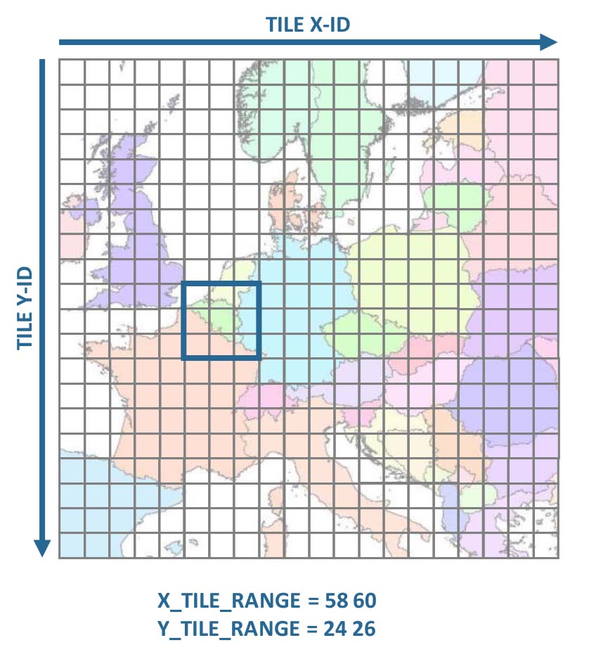
1) The grid
The cubed data are stored in a grid system. Each tile has a unique tile ID, which consists of an X-ID, and a Y-ID. The numbers increase from left ro right, and from top to bottom. In a first step, a rectangular extent needs to be specified using the tile X- and Y-IDs. In this example, we have selected the extent covering Belgium, i.e. 9 tiles.
2) The tile allow-list
If you do not want to process all tiles, you can use a Tile allow-list. The allow-list is intersected with the analysis extent, i.e. only tiles included in both the analysis extent AND the allow-list will be processed. This is optional.

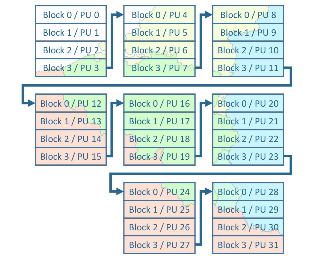
3) The internal file layout
The image chips in each tile have an internal block structure for partial image access.
Before FORCE 3.8.01-dev:::2025-09-17_14:04:58, these blocks were strips that were as wide as the TILE_SIZE and as high as the BLOCK_SIZE.
These blocks were the main processing units (PU), and were processed sequentially, i.e. one after another.
Processing was highly optimized for this block structure, allowing for efficient memory access patterns and minimizing data transfer overhead.
But this also meant that the block size had a significant impact on processing efficiency, and you had to choose wisely.
Not processing on block boundaries was possible, but incurred a significant(!) penalty on efficiency.
With FORCE 3.8.01-dev:::2025-09-17_14:04:58 and later, the internal file layout (blocks) has been decoupled from the sub-tile processing chunks.
This means that the penalty for using a non-optimal block size became less significant.
Blocks are now only used for the internal file layout (e.g. blocks of 256 x 256 px), whereas “chunks” are used for the processing units and are
specified by the user via the CHUNK_SIZE parameter.
Chunks may be smaller than tiles, and do not need to be aligned with the internal block structure.
Also, chunks require two values, i.e., the chunk size in x and y direction.
These chunks are the main processing units (PU), and are processed sequentially, i.e. one after another.
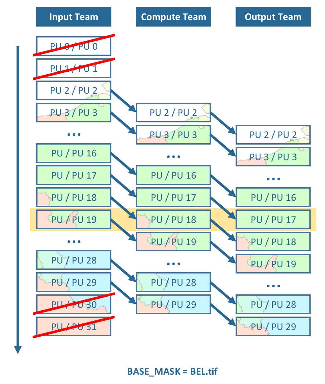
4) Streaming
FORCE uses a streaming strategy, where three teams take care of reading, computing and writing data. The teams work simultaneously, e.g. input data for PU 19 is read, pre-loaded data for PU 18 is processed, and processed results for PU 17 are written - at the same time. If processing takes longer than I/O, this streaming strategy avoids idle CPUs waiting for delivery of input data. Optionally, Processing masks can be used, which restrict processing and analysis to certain pixels of interest. Processing units, which do not contain any active pixels, are skipped (in this case, the national territory of Belgium).
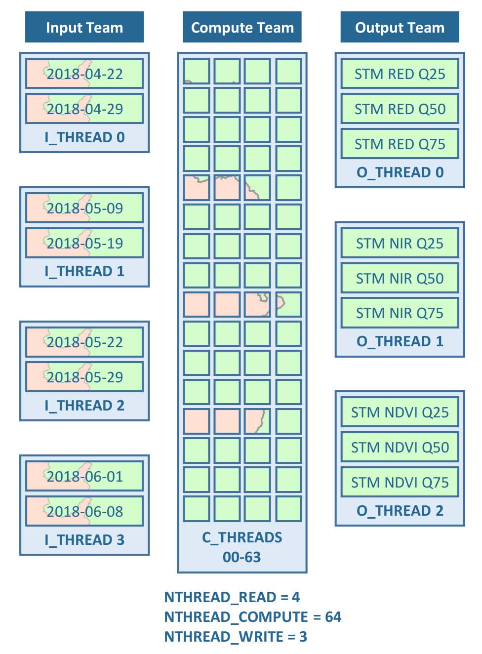
5) Nested parallelism
Each team can use several threads to further parallelize the work. In the input team, multiple threads read multiple input images simultaneously, e.g. different dates of ARD. In the computing team, the pixels are distributed to different threads (please note that the actual load distribution may differ from the idealized figure due to load balancing etc.). In the output team, multiple threads write multiple output products simultaneously, e.g. different Spectral Temporal Metrics.